21+ er diagram definition
Such a picture serves two purposes. ER diagrams are visual tools that are used in the Entity-Relationship model initially proposed by Peter Chen in 1976 to create a uniform convention that considers both relational database.
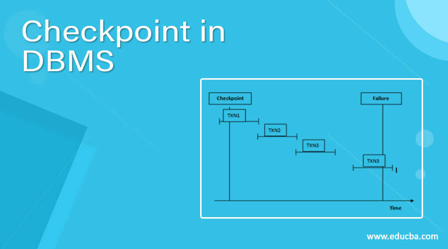
Checkpoint In Dbms How Checkpoint Works In Dbms
Usually it visualizes the information in database.
. The entity relationship model ERM is a computational model that describes the knowledge shape of a difficulty domain in terms of system and connections. Physical ER models show all table. An entity-relationship diagram is a visual tool designed for readers to understand the relationships of entities within a system.
Entity Relationship Diagram commonly known as ERD or ER Diagram or ER model is one type of structural diagram used in database design. Heres how it might work. Entity diagrams are commonly used in software engineering.
An ER diagram is a pictorial representation of the information that can be captured by a database. Up to 24 cash back An entity-relationship diagram ER Diagram is used for this very purpose. It contains different symbols and.
A specialized usually dynamic chart that illustrates the relationships between entities in a database using a specific set of database-specific symbols. The endoplasmic reticulum ER is a vast network of membrane-limited channels that is found in the cytoplasm of the majority of animal cells or ER. A faculty member can only chair one department.
Converting ER to DDL While the main goal of an ER diagram is to picture the relationships we often use the diagram to guide our definitions of the tables. Entity-Relationship ER Diagrams 21 STUDENT DEPT FACULTY CHAIR_F All departments have a faculty member who serves as the chair. It allows database professionals to describe an overall.
Up to 24 cash back Entity-relationship modeling or ER Diagram symbols are part of a conceptual approach to design that models objects as abstract data types and the relations. An entity relationship ER diagram shows how people objects or concepts relate to each other within a process or system. The physical data model is the most granular level of entity-relationship diagrams and represents the process of adding information to the database.
It allows you to create a new database or document an existing one to.

Art Gallery Database Management System Er Diagram 34 Pages Explanation In Doc 1 9mb Updated Learn With Jordan

Er Diagram University Database Relationship Diagram Diagram Templates

Crispr Prokaryotic Adaptive Immune System Crispr Cas9
Ex99 1 026 Jpg
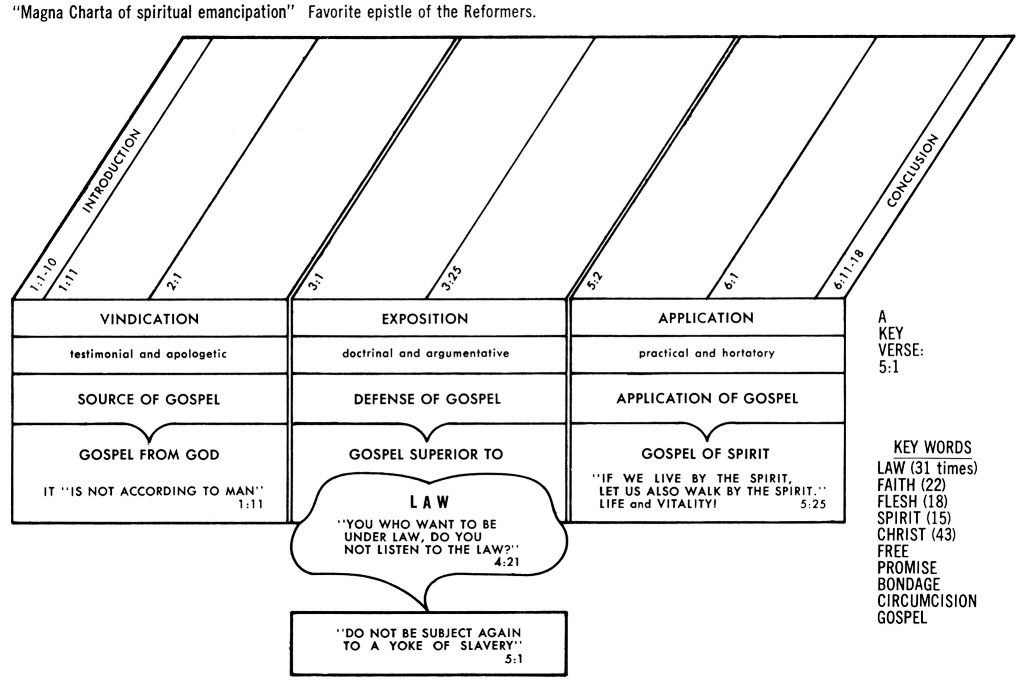
Galatians 1 Commentary Precept Austin
![]()
Dbms Transaction Processing How To Process The Transaction In Dbms
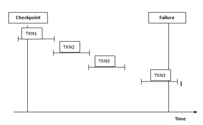
Checkpoint In Dbms How Checkpoint Works In Dbms

Entity Relationship Diagram Erd Er Diagram Tutorial Relationship Diagram Activity Diagram Tutorial

Cost Benefit Analysis Comparing Trough Two Level Auc And Bayesian Auc Dosing For Vancomycin Clinical Microbiology And Infection
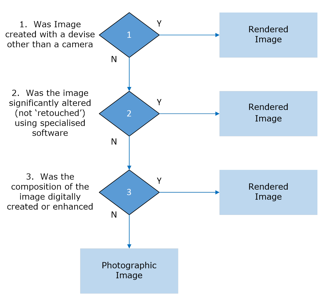
Gs1 Product Image Specification Standard Gs1

Admin And User Chen Er Diagram Relationship Diagram Data Modeling Diagram

Er Diagram Of Movie Theatre Relationship Diagram Diagram Interactive Design

Er Diagram For One To Many Relationship Relationship Diagram Diagram Relationship
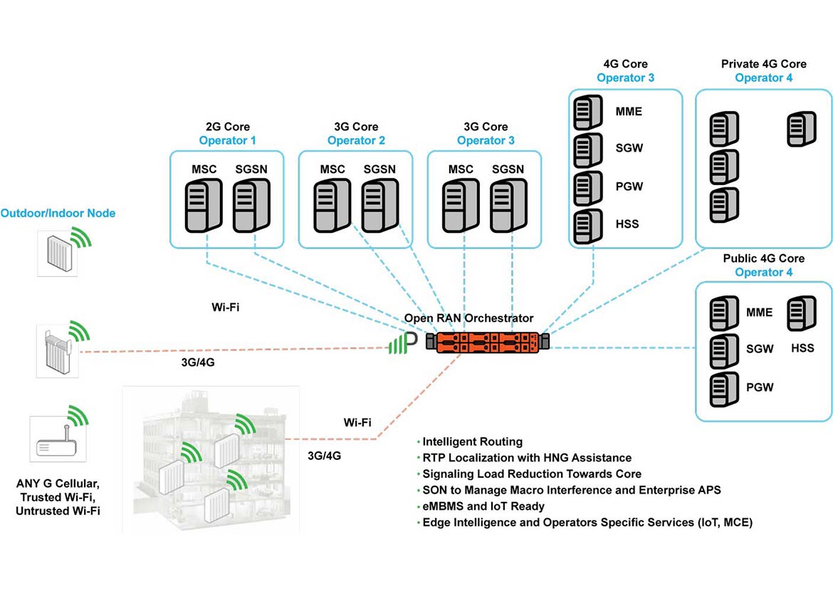
Multi Operator Core Networks Mocn Parallel Wireless

A Text Message Intervention To Reduce 21st Birthday Alcohol Consumption Evaluation Of A Two Group Randomized Controlled Trial

Er Diagram University Database Relationship Diagram Diagram Templates

Cost Benefit Analysis Comparing Trough Two Level Auc And Bayesian Auc Dosing For Vancomycin Clinical Microbiology And Infection